


Today is just a short reminder, again, to not use layers to control visibility with Civil 3D objects. I’m doing a project where I was given a file that had contours (same at elevation but most were not), text next to 2 lines in an X arrangement, spot elevations that were pointing to random spots along a curb line, etc. I would have hoped this came from an exploded version of the Civil 3D model, but with other factors like layer naming, I was not hopeful. So I set off to build the surface from scratch.
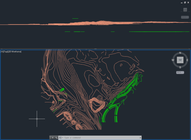
Initially, I looked at the contours. So I isolated those layers and split my view so I could understand which “lines” were at the correct elevation. In one view I used a TOP orientation and the other view used a LEFT/RIGHT/FRONT/BACK view. In this “side” view, it was easy to see the bad elevations. So I changed the color of those objects to something in contrast to the layer color. As I made the appropriate elevation change, I set the object color back to BYLAYER.
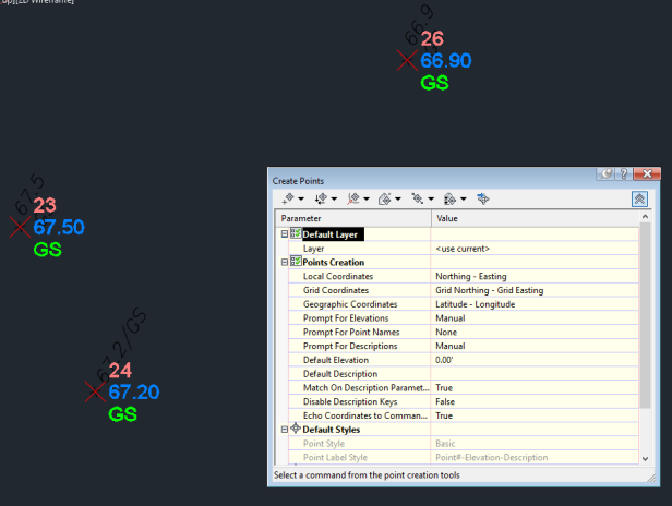
Next up were spot elevations. I had a single Mtext with 2 lines forming an ‘X’ indicating the location of the elevation noted in the text label. What to do here… My first thought was to create a dynamo script, but it was only about 100 or so points. So I set the point creation settings (automatic description, manual elevation) and set the OSNAP to intersection. It went rather quickly even though it was quite monotonous.
Wait, I thought you said this was a quick reminder about layer management of civil objects. It is… Wait for it……
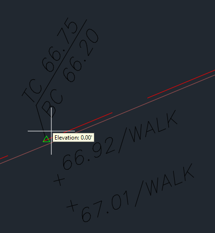
Last objects I needed to create were feature lines representing curb and other hard edges. I simply joined all contiguous lines as much as possible with zero elevation. I intended to use Quick Elevation Edit to run down each feature line as quick as possible to add the elevation data. By this time, I had used Layer Isolate to have the feature line layers ON and the 2D CAD layers ON as well. When I went to edit the elevations, the tooltip would show the elevation or grade of the feature line as expected. However, the green glyph indicating which vertex or slope I was editing was NOT visible. Did I mention I was given this file? Initial reactions were that it was a setting in the file. Then, for some reason, I used layer Unisolate and tried again. Voila! Green glyphs were now visible? Great… It’s a layer thing. See, I told you…

But there was way too much going on, I needed the isolation to read the labels and pick the right spots. So I returned to my previous layer state and tried turning certain layers I thought might be used to show those glyphs. No luck at all. So I started to go through and turn individual layers ON one at a time to find the needle in the haystack, starting with layer zero. To my surprise, this was the layer! How random. After all that pain, I thought I should capture this little bit of knowledge and share with others that may have had similar troubles.
The moral of the story? Don’t use layer states to control civil 3D objects, chaos will likely find you!


I think we could argue about “to layer or not to layer”, but when you have 4-9 people in a project and all on different tasks, you can’t be going back into xrefs and changing styles of components to adjust visibility. I think you could have received a file that wasn’t fully thought out. We still get drawings that are using upside down and rotated Z axis because people can’t figure out Northing (y)/ Easting (x) is actually Easting (x), Northing (y) in CAD.
LikeLike
Agreed. I am more speaking to On vs Off visibility when everything is in one file. Hopefully, you’ve put objects in their own independent xref. That way, object components are on layers that can be tweaked for conditions. If i need an object to display using 2 or more different styles, they likely are supporting different types of plans, like a surface for a basemap vs a surface for steep slopes. I’d simply make 2 XREFs withe a surface DREF and set the appropriate style.
Really, C3D provides a nice spec house that you can decorate any way you like. 🙂
LikeLike
Did the civil 3d objects in question have layers within the styles? Is that what you mean by using “layers to control visibility with Civil 3D objects”.
If so, I agree that unless absolutely necessary to do otherwise, all civil 3d styles should have all layers set to 0 within the styles. Then use the object layer that the civil 3d entity resides on to control visibility. Anything else results in paradoxical behavior when trying to use normal autocad commands on the objects, like freezing the object layer but the entity is remains visible because the display layer as set in the civil 3d style is still on.
LikeLike
Hi Mike. Some folks prefer their objects behave like blocks that have stuff on specific layers so they always look as expected. Others have no issue with preseting the component color, linetype, etc. in the style while using layer 0. Your method is almost mandatory for folks that have to work with c3d objects but only have vanilla autocad for production.
Thanks for the note. I’ve so busy the past year or so, the blog content has been idle. Hoping to have time this year to share more knowledge!
LikeLike
Thanks, but I still don’t quite understand what the core issue was in your post. You can set properties in civil 3d styles so they always look as expected without using layers within styles. My method is almost mandatory just for me working with styles that I created working in Civil 3d, because otherwise one must to go to the layer properties window to adjust the display layer (and remember what that display layer actually is).
There is a bug I have encountered in many versions of civil 3d where the civil 3d objects are sensitive to the active layer in the current drawing, especially for plotting. Maybe your active layer was 0. I’m using civil 3d 2017 SP 1.1… can’t reproduce the problem right now.
LikeLike
The issue was that c3d uses layer zero to display the green glyph when editing feature lines.
LikeLike
I realize I’m a little late to the party. I was just passing through and saw this post. Been working on our company CAD standards and have been thinking about putting all styles to layer0 as you describe. I’m curious how you handle surfaces, where you might want two different display types for Major and Minor contours?
LikeLike
Well, we have 2 scenarios; one if the objects are on later zero and one if the components are on layer zero. If we put the objects and the components in the object style on layer zero, we loose all control. So only 2 scenarios to evaluate.
Object layer = zero
In this scenario, we are thinking about the components driving the display. For components, we can set them to layers, thereby letting layer property changes propagate to the components. Or we can set them to zero and hard coding color, linetype, etc. properties.
Component layer = zero
In this scenario, we typically are putting the objects on a specific layer. When the components are on layer zero, the components reflect the object layer; just like a block.
So, which method should we use? Well, it depends. Styles that require the components to be presented differently, we’re likely setting object layer to zero. Why not just use a layer in this scenario? In sheet files, layer freeze is often used. This historically would not work with the object layer NOT set to zero. Alternatively, styles that do not require components to be presented differently could have the component layer set to zero.
Clear as mud? The short answer is c3d objects act like blocks. So that should help with your planning. Good luck!
LikeLike